Four-Bit LED Calculator
A Hardware Implementation Using Half Adders, Breadboards, and LEDs
Project Overview
This project demonstrates a four-bit binary adder circuit implemented using discrete electronic components. The calculator takes two 4-bit binary numbers as input (each ranging from 0 to 15) and displays their sum using LEDs. The circuit is built on breadboards using half adders, LEDs, resistors, and jumper wires, providing a hands-on approach to understanding digital logic and binary arithmetic.
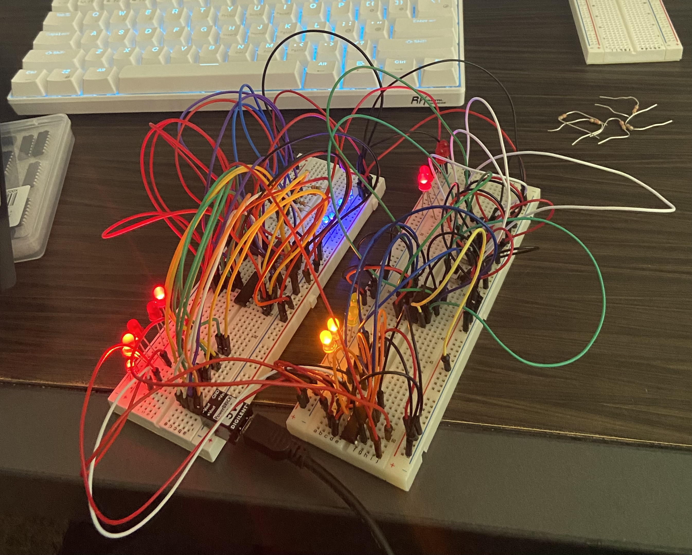
Physical implementation of the four-bit LED calculator on breadboards
Understanding Half Adders
What is a Half Adder?
A half adder is a fundamental digital logic circuit that performs addition of two single binary digits. It takes two inputs (A and B) and produces two outputs: the sum (S) and the carry (C).
How Half Adders Work
The half adder implements the following logic:
- Sum (S): The sum output is the XOR (exclusive OR) of the two inputs. This gives us the least significant bit of the addition result.
- Carry (C): The carry output is the AND of the two inputs. This represents when both inputs are 1, requiring a carry to the next bit position.
Half Adder Truth Table
| Input A | Input B | Sum (S) | Carry (C) |
|---|---|---|---|
| 0 | 0 | 0 | 0 |
| 0 | 1 | 1 | 0 |
| 1 | 0 | 1 | 0 |
| 1 | 1 | 0 | 1 |
Building a 4-Bit Adder
To create a 4-bit adder, we chain multiple half adders together. For each bit position (0 through 3), we need to add:
- The corresponding bits from Input A and Input B
- Any carry from the previous bit position
In practice, full adders (which handle three inputs: A, B, and carry-in) are often used for bits 1-3, while a half adder can be used for the least significant bit (bit 0). However, this project demonstrates the concept using half adders as building blocks.
Breadboard Wiring Guide
Component Layout
The circuit is constructed across multiple breadboards, with careful attention to power distribution and signal routing.
Power Distribution
- Power Supply: A DIGILENT PowerBRICK module provides regulated 5V power to the circuit via USB connection.
- Power Rails: The breadboard's power rails (typically red for VCC and blue/black for GND) distribute power and ground throughout the circuit.
- LEDs: Each LED requires a current-limiting resistor (typically 220Ω to 1kΩ) connected in series with the anode (longer leg) to prevent damage.
Input Configuration
- Input A (4 bits): Four switches or input pins control the four LEDs representing the first 4-bit number. Each bit is independently controlled.
- Input B (4 bits): Similarly, four switches or input pins control the second set of four LEDs.
- Each input LED is connected through a resistor to ground, with the input signal controlling whether current flows.
Half Adder Implementation
- IC Chips: Half adders can be implemented using integrated circuits such as the 74LS86 (XOR gates) and 74LS08 (AND gates), or using discrete logic gates.
- Bit 0 Addition: The least significant bits (A₀ and B₀) are fed into a half adder, producing Sum₀ and Carry₀.
- Subsequent Bits: For bits 1-3, the addition must account for the carry from the previous bit. This requires either full adders or cascaded half adders with additional logic.
- Output LEDs: The sum outputs from each bit position drive the corresponding output LEDs through current-limiting resistors.
Overflow Detection
- The overflow LED is activated when the sum of the two 4-bit numbers exceeds 15 (1111 in binary).
- This occurs when there's a carry out from the most significant bit (bit 3).
- The overflow signal is typically generated by detecting when both input bits and the carry-in are 1 at the MSB position.
Wiring Tips
- Use color-coded jumper wires: red for power, black for ground, and other colors for signals to maintain clarity.
- Keep wire lengths short to minimize noise and interference.
- Double-check all connections before applying power.
- Test each half adder stage independently before connecting them together.
- Ensure proper orientation of ICs and LEDs (check datasheets for pin configurations).
Interactive Simulation
Use the interactive calculator below to simulate the behavior of the hardware circuit. Adjust the inputs and observe how the LEDs represent binary values and how overflow is detected.
Input A
Input B
Result
How the Calculator Works
- Binary Representation: Each LED represents one bit in a 4-bit binary number. A lit LED (🔴) represents 1, and an unlit LED (⚫) represents 0.
- Input Range: Input A and Input B can each represent values from 0 (0000) to 15 (1111) in binary.
- Addition Process: The circuit adds the two 4-bit numbers bit by bit, starting from the least significant bit (rightmost), using half adders to compute sums and carries.
- Output Display: The result is displayed in the output LEDs, showing the sum in binary format.
- Overflow Detection: If the sum exceeds 15, the overflow LED lights up, indicating that the result cannot be represented in 4 bits.